Support

Breaking load test
-
1 Applied area
This standard stipulates the procedure for initial management to ensure quality and performance for setting cable tray product standards in our company.
-
2 Definition of Terms
This standard is applied to the test method to prove the quality characteristics of the tray produced by our company.
-
3 Psalter
When testing a cable tray of a certain design, the one with the widest width should be selected and two specimens should be tested.
(If there is a difference in the side rail or rung thickness, height, or the shape of one part, such as a connection part, the design is considered as a different cable tray.) -
4 Shape of span
It is a simple beam type of span, and there should be no obstacles at both ends.
The tray shall not be subjected to any load in the lateral direction. The length of span should be controlled with ±38(mm)(1 ½ inch) precision. -
5 Position of the specimen
Specimens shall be tested in a horizontal state. The total length of the specimen should not be more than 1.2 times the span length.
-
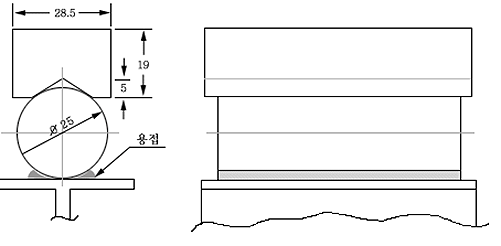
6 Support fixture
The support used to support the end of the specimen is a steel bar with a cross section of 19×28.5 mm (1/8×3/4 inch) as shown in Fig. The depth is 4.7 mm (3/16 inch). The V-groove of the support is hung on the round bar with a diameter of 25.0mm (1 inch), and it is fixed by welding.
-
7 Load material
For the required load, use a steel strip, lead ingot or other materials. The steel bar should not have sharp edges, be 3.1mm (0.125inch) or less thick, and have a width of 28.5mm (1 1/8 inch) to 50.8mm (2 inch) and a length of 1.121mm (4 feet) or less. . By connecting 5 lead ingots, a load of about 560mm (22 inch) length can be used. The material generally has a hexagonal cross-section and is about 760 mm (3 inches) in diameter. Other loading materials must weigh not more than 4.5 kg (10 pounds), have a width of not more than 50.8 mm (2 inches), and a length of not more than 305 mm (12 inches).
-
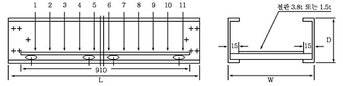
8 Weight
All specimens are loaded as shown in Fig. 2 until they fail. The load is applied in 10 steps at minimum equal intervals. The load should be uniformly distributed in the length and width directions, and the load should be placed between 12.7mm (1/2 inch) from the inner end of the side rail. When testing the ladder type cable tray, it is allowed to cover the bottom with a wide iron plate with a thickness of 3.8mm (gage No. 9) or 1.5mm (gage No. 16). The length must be within 91.4 mm (93 feet). The cover should not be fixed to the tray and should be kept at least 12.7mm (1/2 inch) away from the side rail, and the weight of the cover should be included in the load.
-
9 Breaking load
The load at which the tray breaks during the load test is defined as the destructive test load.
-
10 Interpretation of test results
If results are obtained by performing a load test for at least three span lengths, the results for other span lengths can be calculated by interpolation.
The load for the shorter span length than the tested one can be calculated by the extrapolation method, but the extrapolation method is not applied to the longer span. -
11 Data cleanup
The results obtained from the test shall be recorded in the breaking load test report.
-
12 Maintenance of test records
Stored for 3 years