Support

Welding work
-
1 Purpose
This procedure describes the welding operation procedure for cable tray assembly.
-
2 Applied area
This procedure is applicable for CO2 or shielded arc welding of materials with a thickness of 4.6mm or less, including steel plates or steel rods including cable tray cold-formed structures.
-
3 References
AWS D 1.3
-
4 Definition of Terms
4-1 Welding Procedure Specification (WPS)
This is a welding procedure written to give instructions to the welder during the welding operation.
4-2 Welding Procedure Certificate (Procedure Qualification Report.: PQR)
Person performing manual and semi-automatic welding operations
4-3 Welder
This is a welding procedure written to give instructions to the welder during the welding operation.
-
5 Type of welding
and application5-1 Groove Welds In Butt Joints
This type of welding is applied to the welding of plate to plate at all points.
5-2 Arc Spot Welds, Pupple Welds
As shown in Table 1, this welding is to weld a flat plate to a thick molded structure in a flat state. do.
5-3 Arc Seam Welds
This welding method is applicable to the following welding including the bonding method in Table 1.
- (1) Welding of plate and thick molded support structures
- (2) Welding of flat plate and horizontal plate
5-4 Flare Croove Welds And Fillet Welds
This welding method can be used for welding in any position, including those described below.
- (1) Welding for 2 steel plates for flare V groove
- (2) Thick forming structure including plate and 2 sheets of swarf and fillet welding method/li>
Material state Butt joint spearfish groove welding Arc spot welding Butt joint spearfish groove welding Arc spot welding Butt joint spearfish groove welding Arc spot welding Iron plate and iron plate Planar Horizontal Vertical Overhead Flat horizontal Planar Horizontal Vertical Overhead ← ← Iron plate
structural support← Plane Plane ↑ ↑ ← 5-5 Material specification
- (1) Hot-dip galvanized steel plate: ASTM A 446 GR A, B, CF, E (KS D 3506)
- (2) Hot-rolled steel plate and rod: ASTM A 570 (KS D 3501)
- (3) Cold-rolled steel plate and rod: ASTM A 606 (KS D 3512)
- (4) Cold-rolled high-sensitivity collobium, vanadium-added low-alloy steel sheet and rod: ASTM A 607
- (5) Cold-rolled short steel plate and rod for machine base : ASTM A 611 (KS D 3517)
5-6 Welding process
- (1) This procedure is for Shield Metal Arc (SMA W), Ras Metal Arc (AS Metal Arc, CMAW), Flux Cored Arc (FCAW) and Submerged Arc Welding ( Sub Merged Arc, SAW).
- (2) When stud welding is performed on a flat point on the ceiling or roof of the steel structure, follow AWS 1-1 Chapter 7 Stud Welding Method.
-
6 Welding method
6-1 Welding General
Welding methods include butt groove welding, arc spot welding at arc seam, lap or fillet welding at T-joint, single flare V-groove welding, etc.
-
7 Welding work
7-1 Test material
- (1) The surface of the material should be smooth and uniform so as not to affect the strength or quality, and there should be no cracks, tears or overlapping marks. Also, when welding the opposite specimen, fume due to other substances, oils and fats, moisture, rust, slag, and thick film should be prevented from occurring. Spatter inhibitor, galvanized film, rust preventive film, oxide film generated during rolling, and residues from iron brushes are acceptable.
- (2) If the material is a galvanized steel plate or other protective coating-treated steel plate, an appropriate exhaust ventilation device should be provided to protect the welder from harmful welding fumes.
- (3) Welding test should be conducted when the ambient temperature is less than -18℃, or when the specimen is too humid or when the working conditions such as rain, snow, and strong wind are unsuitable.
7-2 Welding equipment
- (1) The defect status is detailed in Annex 1.
- (2) The joint of the weld should be connected so that it is in full contact with the welder.
7-3 Welding condition setting
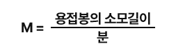
To implement normal welding conditions, the welding current is adjusted appropriately, and the current condition for shielded metal arc welding is set to the melting degree described in the Procedure Qualifcation. In case of shielded arc welding, gas metal arc welding, or submerged arc welding, the current condition is adjusted by monitoring the ammeter (A) and feeding speed of the welding wire.
7-4 Weld quality
Inspect the welding position, size, length and bead shape, and undercut in the growth state according to the drawing or specification sheet.
7-5 Set the pass/fail judgment criteria
- (1) Visually inspect the specimen.
-
(2) Welds must satisfy all 4 items of the following criteria.
- 1) No cracks
- 2) In all places such as square grooves, arc channels, arc threads, etc., at least 1mm of weld skin must be developed.
- 3) The accumulated length L is the specified length of the weld or, in the case of arc scort welding, the penetration of the base metal and the skin of the weld material, so the depth of the undercut is not subject to inspection, and it is judged as defective when an overwelded hole occurs.
- 4) The fillet weld surface shall be smooth and unobtrusive.
-
8 Welding
8-1 Welding
- (1) In the case of grooved butt welding, the mixing ratio of electrode, gas, and solvent shall be carried out according to Table 2.
- (2) For welding other than 9.1, use the electrode, gas, and material mixing ratio equal to or higher than the tensile strength of the material to be welded.
8-2 Electrode in shield metal arc welding
(The electrode for SMAW complies with the requirements of the latest version according to AWS A 5.1, A 5.5, etc. All electrode types have a low hydrogen content as stipulated in AWS A 5.1, and dry at 230°C to 250°C for 2 hours before use or store in a moisture-proof container. buy what has been
8-3 At the request of the technician, the supplier shall attach a certificate of satisfaction stating that the condition required for the relevant classification item of the electrode is satisfied.
8-3 At the request of the technician, the supplier shall attach a certificate of satisfaction stating that the condition required for the relevant classification item of the electrode is satisfied.
 Appendix 6 describes how this melt ratio is applied.
-
9 Certification
9-1 Welding Procedures Qualifications
For each welding procedure, the procedure specification for each type of welding should be prepared as shown in Table 3.
9-2
(For each welding procedure, as shown in Table 3, the procedure specification for each type of welding must be prepared, and it must be submitted upon request for approval from the contractor to obtain approval.
The implementation of the procedure specification (PQR) is carried out in accordance with Annex 1. If you have previously obtained prior certification, you can start working.9-3 Requirements for Procedural Qualification (PQR)
Welding procedures should check the scattering that occurs.
9-4 Validity of Certification
When the approval of welding procedure certification (PQR) is obtained from the contractor, the same work is continuously recognized, but re-approval must be obtained in the case of changes in the essential items presented in Paragraph 9-5.
9-5 Recertification required
- (1) Change of classification class of welding rod (when changing from E6010 to E6020)
- (2) When changing the size of the welding rod
- (3) When the melting rate ratio is changed or the current and rapid feed rate are changed by more than 10%
- (4) When changing the welding polarity
9-6
For the welding procedure certification (PQR), the number of samples required, test method, and judgment method, etc. shall be carried out as in Attached Table 1.
-
10 Record and management
The quality control department shall implement and maintain the following records for certification of welding work.
10-1 Welding procedure specification
10-2 Welding Procedure Certificate
10-3 Welder Qualification Test Record
10-4 welder welding record
The above records shall be kept until the required period if there is a request from the contractor to keep the quality assurance, and if there is no request, it will be kept for 3 years.
-
11 Asterisk 1
Procedural certification examTable 1- Procedure Qualification Tests Test Assemvlies
Shown in figureType of Welded
Joint TestedNumber of tests required
for each welding position
thickness and type of coatingType of Test Qualifies For 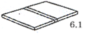
Square groove butt joint Sheet to sheet each position of welding 2 Bend Square groove butt joint, sheet to sheet, position used in test 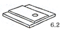
Arc spot weld Sheet to supporting member, that position 2 Twist Arc spot weld and arc seam weld, sheet to supporting member, flat position 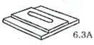
Arc seam weld Sheet to supporting member flat position 2 Bend Arc seam weld, sheet to supporting member, flat position 
Arc seam weld Sheet to sheet horizontal position 2 Bend Arc seam weld, sheet to sheet, horizontal positon 
Fillet welded lap joint Sheet to sheet, any position 2 Bend Fillet welded lap joint, sheet to sheet, or sheet to supporting member, position tested 
Fillet welded lap joint Sheet to supporting member, any position 2 Bend Fillet welded lap joint, sheet to supporting member, position tested No data
-
12 Asterisk 2
Welder
certification examNo data