Support

Connection electrical resistance, hot-dip galvanizing test
-
1 Applied area
This procedure specifies the procedure for testing whether the connection part of the part where only the cable tray is interconnected (connected with a connector) is sufficiently electrically connected.
-
2 Test conditions and test items
4-1 Exam conditions
- (1) Power supply condition AC 100V or AC 220V, 60HZ power supply
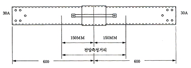
- (2) Load Electrical equipment having a rated current of 30A when the power of (1) is applied
-
(3) Voltage and ammeter
When a circuit is constructed, it must be precise as it can measure voltage and current.
Remark) It is okay to use the bridge method for this test if the equipment is ready.
4-2 Test item
-
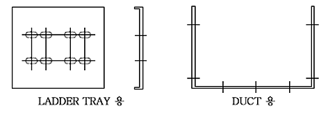
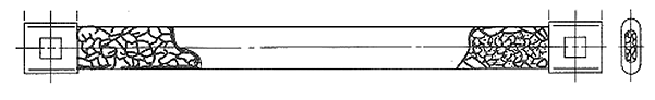
(1) Cable trays and ducts
Type Ladder Solid Type W width Not specified L Length 600 mm 600 mm 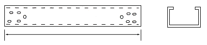
[ Cable Duct ] 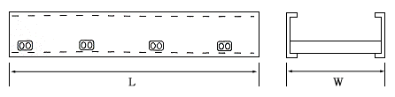
[ Cable tray ] -
(2) Joint Connector
Remark) Dimensions are in accordance with the approved drawings.
-
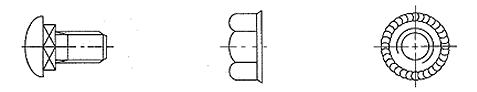
(3) Connection bolts and nuts
-
(4) Crounding Bonding Jubper
Remark) Dimensions and SQ are in accordance with the approved drawings.
-
3 Preparation of specimens for testing
- 3-1
- Connect two cable trays (or ducts) having a length of 600mm using a joint connector to firmly connect the connecting bolts and nuts.
- 3-2
- Connect the side rails of the connected cable trays (or ducts) to each other with a Grounding Bonding Jumper.
- 3-3
- The above connection must be a mechanical connection and must not use any other method.
(Generally the same as how to connect when installing a cable tray)
-
4 Test and measurement
- 4-1
- Pass a current of 30A through the ends of both side rails of the finished test piece, measure the voltage with a voltmeter at a distance of 6" (150mm) from both side rails connected, and based on this, the resistance of the tray (or duct) connection to calculate
-
5 Test result
- 5-1
-
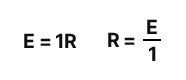
As the voltage of the voltmeter measured as in section 4, the voltage increase between both ends is measured, and when this is divided by the current value of (30A) measured by the ammeter, the resistance value between both ends is calculated.
- 5-2
-
According to the above calculation, the resistance value should not exceed 0.00033Ω.
Remark) In the above test, the voltage drop should not exceed 9.9mm at most.